Why an amp rating is only one part of the choice
A standalone solar charge controller manages DC charging in a system where the AC inverter is a separate device. Choosing the highest charging-current number does not settle the battery voltage, permitted solar input or battery charging requirements.
Read the labels rather than treating every current or voltage figure as interchangeable. The manufacturer tables below list maximum charging current separately from solar-input voltage and power. The charging-current row does not provide a PV input-current rating or an inverter AC output rating.
Does the exact controller support your battery voltage? Are the proposed solar input conditions within its documented limits? Can its charging settings meet the exact battery’s requirements? A yes to one does not answer the others.
PC1800A and PC1800F: keep the voltage qualifications
These Toyama catalogue families illustrate how a series table can combine several variants. The figures below are published manufacturer values, not measured results or a complete system design.
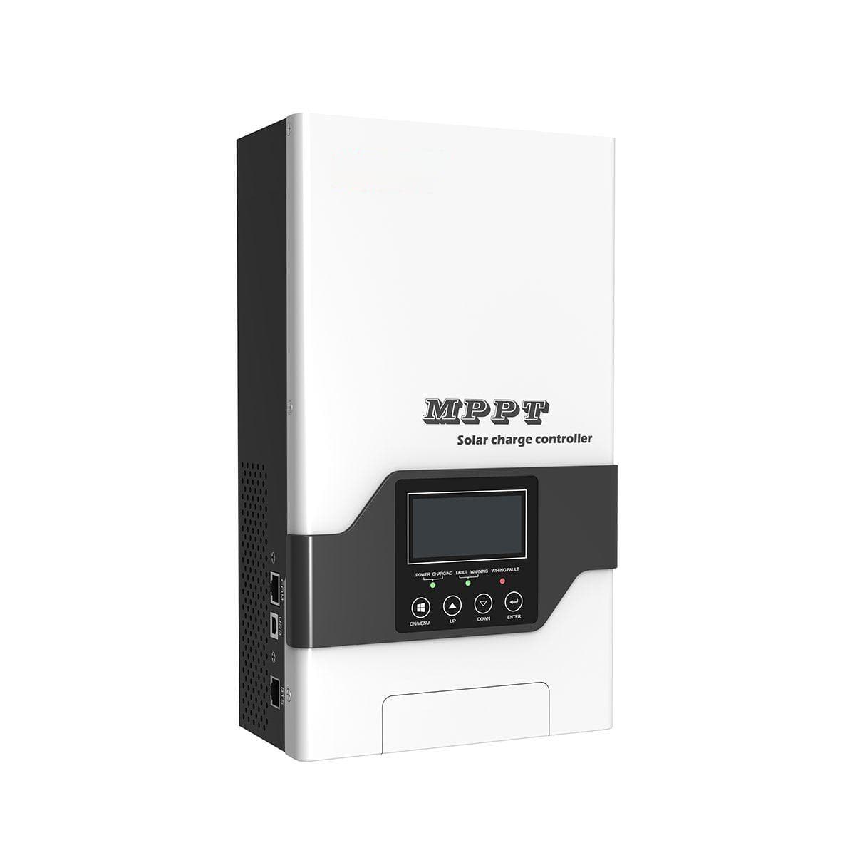
| Published detail | PC1800A | PC1800F |
|---|---|---|
| Model variants | PC18-3015A / PC18-4015A | PC18-6025F / PC18-8025F / PC18-10025F |
| Maximum charging current | 30 / 40 A | 60 / 80 / 100 A |
| Nominal battery voltage | 12 / 24 V, automatic detection | 12 / 24 / 48 V, automatic; 36 V requires a setting |
| Solar voltage limit | Maximum PV open voltage: 145 VDC | Maximum solar input voltage: 245 VDC |
| Numerical MPPT range | 60–130 VDC | Not listed in the referenced summary table |
| Maximum PV input power | 30 A variant: 432 W at 12 V / 864 W at 24 V. 40 A variant: 576 W at 12 V / 1,152 W at 24 V. | 3,760 / 5,000 / 6,250 W for the three variants, explicitly listed at 48 V. |
The PC1800F power row is labelled 48 V. Do not reuse those figures as 12 V or 24 V ratings. Likewise, its page describes a wide MPPT range but does not give the numerical window in the referenced table; the PC1800A window cannot fill that gap.
Primary sources: PC1800A manufacturer specifications and PC1800F manufacturer specifications. Confirm the exact model and current documentation before final selection.
What the summary table cannot confirm
Battery voltage support is not proof of compatibility with a particular battery chemistry, charging profile or communication system. Ask for the battery manufacturer’s permissible charging settings and the controller’s exact supported settings. A communication connector alone does not establish a supported battery pairing.
For the solar side, provide the panel model and nameplate details. Ask the project designer to check the controller’s voltage, operating-window, input-current and power requirements against the proposed array and site conditions. This article does not specify string wiring, electrical protection or installation settings.
If replacing equipment, include the existing controller and inverter models. A standalone controller is a charging component; it does not replace the inverter that supplies AC loads. Read the off-grid power guide for the wider equipment brief, and battery energy and compatibility guide for separate storage questions.
What to send with your controller enquiry
- The exact controller variant you are considering, or the model being replaced.
- Battery model, nominal voltage and manufacturer charging requirements.
- Solar panel model and nameplate details; include an existing design if available.
- Existing inverter model and the intended role of the standalone controller.
- Site location and equipment environment, including any constraints your designer has identified.
- Any unresolved question, such as the PC1800F operating window or input limits at your battery voltage.
You can request clarification before choosing a variant. Pricing, availability and configuration remain enquiry questions; the comparison does not establish stock or a verified system package.
Compare MPPT controllers →Contact Toyama in Dubai with the model details and your requirements.